
5 Electrochemistry: Voltaic Cells
Introduction
We have previously seen reactions involving the transfer of one or more electrons from one species to another, typically called oxidation-reduction reactions or, more colloquially, redox reactions. Since redox reactions involve the transfer of electrons, they are also accompanied by changes in the oxidation states of the reactant and product. The reactant that donates the electron is dubbed the reductant, while the species that accepts the electron is dubbed the oxidant.
We often think of redox reactions as occurring through two half-reactions. Specifically, we can consider the oxidation half-reaction and the reduction half-reaction. As an example, let’s consider a reaction that you did last semester as part of the “Copper Cycle” experiment:
| CuCl2(aq) + Zn(s) → Cu(s) + ZnCl2(aq) | (1) |
which can be rewritten as the net ionic equation
| Cu2+(aq) + Zn(s) → Cu(s) + Zn2+(aq) | (2) |
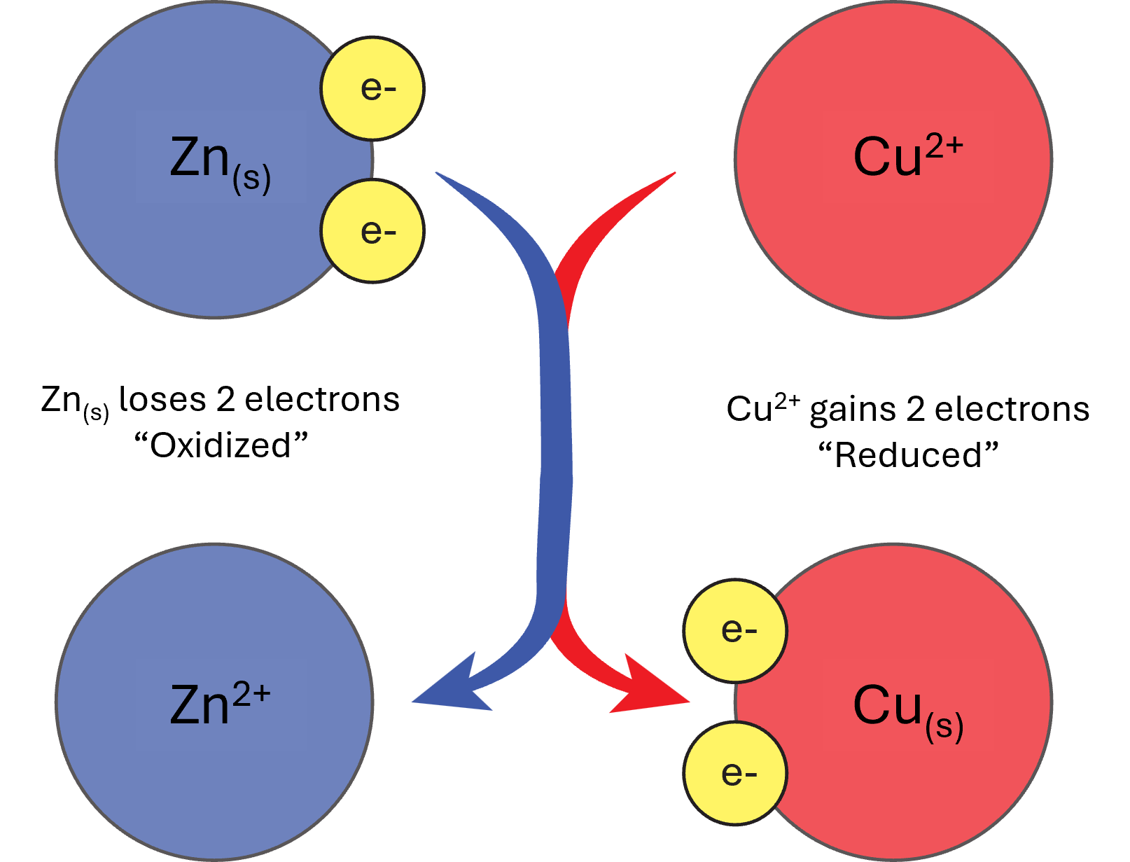
This is an example of a single displacement reaction in which the solid zinc gives up two electrons to the copper ion to form solid copper and a zinc ion. Since we know that the zinc is being oxidized and the copper is being reduced, we can write the individual half-reactions as in equations 2 and 3.
| Cu2+(aq) + 2e– → Cu(s) | (3) |
| Zn(s) → Zn2+(aq) + 2e– | (4) |
It’s important to notice here that the chloride ions have been left out of the half-reactions. This is because the chloride ions are not important to the reaction and are merely included simply for charge balancing purposes. Additionally, if you add the two half-reactions together, you’ll notice that the electrons will “cancel out” and you’ll be left with just the net ionic equation. Remember that no half-reaction can occur by itself — both half-reactions are occurring simultaneously, because the electrons have to travel from the neutral zinc species to the ionic copper species as outlined in Figure 1.
One important aspect to consider regarding redox reactions is the reduction potential of the species undergoing electron transfer. Most often measured in volts, V, reduction potential measures the tendency for a redox reaction to occur. Under standard conditions, 25°C, and 1.0 M concentration of the aqueous ions, the measured voltage of the reduction half-reaction is defined as the standard reduction potential, E°. Thankfully, standard reduction potentials are well-tabulated and readily available from online sources and most chemistry textbooks/review papers.1
When you are looking at tabulated standard potentials, it’s important to keep in mind that the values are determined with respect to that ion’s ability to accept electrons (be reduced). To better understand this, let’s go back to our example with zinc and copper. The only difference here is that we will need to rewrite equation 4 to show the zinc ion being reduced by two electrons.
| Cu2+(aq) + 2e– → Cu(s) E° = 0.3419 V | (5) |
| Zn2+(aq) + 2e– → Zn(s) E° = -0.7618 V | (6) |
Now we now how the standard reduction potentials compare to one another! But…what do these actually mean? The values are determined as compared to a standard hydrogen electrode (SHE), meaning negative values are stronger reducing agents than an SHE, while positive values and stronger oxidizing agents than an SHE. Therefore, by comparing equations 5 and 6, we can say that copper is the stronger oxidizing agent, meaning Cu2+ is more likely to accept electrons, while Zn2+ is more likely to donate electrons.
In the “Copper Cycle” experiment from last semester, this reduction was carried out in a single solution, resulting in a very fast reaction that forms solid copper. If we want to utilize the electric potential, the electrons being transferred must be channeled through a conducting wire so that the current can be controlled. This is the basis of a voltaic cell (also referred to as a galvanic cell). A voltaic cell consists of two separated aqueous solutions of the ions involved in the half reactions that are connected by a salt bridge. Additionally, each solution contains a solid, metallic form of the species in the half reactions that are connected by the conducting wire (Figure 2).
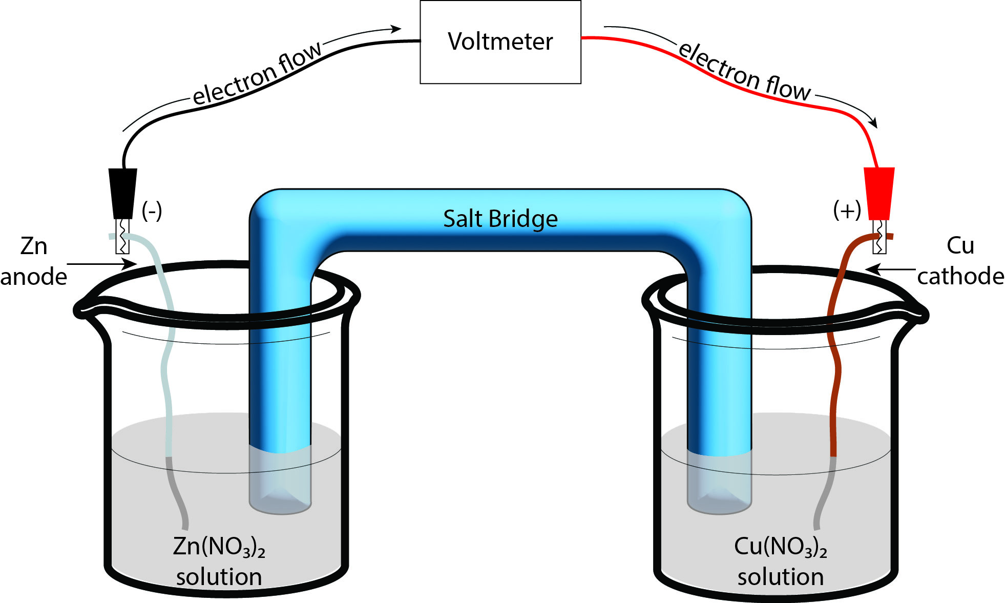
The salt bridge can be comprised of numerous objects — oftentimes the bridge will be a gelled salt solution, but can be as simple as a piece of string soaked in a salt solution. The important factor is that the bridge must contain a salt that does not appear in either of the half-reactions of interest. The electrolyte-soaked bridge allows charge to travel from one solution to the other. We are then able to connect the conducting wires to a system that requires electrical current. In essence, we’ve made a battery using two salt solutions!
Standard Conditions, Cell Potentials, and the Nernst Equation
Under standard conditions, we can predict the cell potential, E°cell, based on the half-cell reduction potentials that we’ve seen above in equations 5 and 6. E°cell is a measure of the theoretical voltage that a battery can provide and will likely deviate from the actual measured potential. The cell potential can be calculated following equation 7:
|
[latex]\text{E}^\circ_{\text{cell}} = \text{E}^\circ_{\text{cathode}} - \text{E}^\circ_{\text{anode}}[/latex] |
(7) |
Now that we know the standard reduction potentials for both copper and zinc, we can calculate the overall cell potential by simply plugging the values into equation 7
|
[latex]\text{E}^\circ_{\text{cell}} = +0.34 \text{ V} − (−0.76 \text{ V}) = +1.10 \text{ V}[/latex] |
(8) |
You may recall from our previous discussions of thermodynamics that a negative Gibbs free energy (ΔG°) is indicative of a spontaneous reaction. The relation between Gibbs free energy and standard cell potential is given by ΔG° = − nFE°cell, where F is Faraday’s constant (96,500 J/(V•mol). The positive voltage for E°cell indicates that at standard conditions the reaction (specifically the donation of electrons from Zn(s) to Cu2+) is spontaneous.
While the E°cell value gives us valuable insight into the spontaneity of the cell, we are most often not working under standard conditions. In this case, we can adjust the standard cell potential we previously calculated by using the Nernst equation.
| [latex]\text{E}_{\text{cell}} = \text{E}^\circ_{\text{cell}} - \frac{RT}{nF} \ln(Q)[/latex] | (9) |
We know that R (the universal gas constant, 8.314 J/(mol•K)), T (assumed to be room temperature, 298 K), and F are constants, so we can rewrite equation 9 as
| [latex]\text{E}_{\text{cell}} = \text{E}^\circ_{\text{cell}} - \frac{0.0592}{n} \ln(Q)[/latex] | (10) |
| where [latex]Q = \frac{\text{[ion products]}}{\text{[ion reactants]}}[/latex] | (11) |
Tips and Tricks: For concentration cells like the one you will build in Part 3 of today’s experiment, it can be tricky at first to see which side of the cell is the products and which is the reactants. So for a concentration cell, Q is defined as [X]anode/[X]cathode, where X is the ion in the anode and cathode, respectively.
Experiment Overview
During this experiment, you will be exploring the basics of redox reactions by constructing a series of microscale voltaic cells. By developing an understanding of the basics of voltaic cells, you will learn how you can determine the identity of an unknown metal, as well as how the theoretical cell potential differs from the measured cell potential in a concentration cell.
Safety and Waste Disposal
You will be using a variety of electrolyte solutions during this experiment, along with the solid forms of copper and zinc. All waste should be disposed of in the inorganic waste jugs in the fume hood. As with any other wet experiment, proper PPE is required (shirt that covers your shoulders and midsection, long pants that cover your ankles, and closed-toe shoes), as well as chemical splash goggles and nitrile gloves. As always, nitrile gloves are provided in lab and can be found by the sinks.
When you are finished with the experiment, the solid metal pieces used as electrodes should be returned to their respective containers. Be sure you do not get the metals mixed up! Ask your TA if you are confused about where your electrodes should go. It will likely be easiest to keep a 1 L beaker at your station to serve as a waste container, as this will allow you to rinse your well plate with DI water at your station. Once you are finished with the experiment, you may pour your individual waste container in the inorganic waste jugs in the fume hood.
Copper(II) nitrate is an inorganic salt that forms a deep blue solution upon dissolving in water. You will be working with two different concentrations of copper(II) nitrate, 0.10 M and 0.050 M, so the more concentrated solution will likely appear a darker blue than the less concentrated solution. It is important that you carefully read all labels of solutions to make sure that you are indeed using the correct solution. In both cases, should any of the copper(II) nitrate solution come into contact with your skin, you should immediately alert your TA and rinse the affected area under running water for at least 15 minutes. Click here to see the SDS.
Lead(II) nitrate is an inorganic salt that forms a pale yellow solution upon dissolving in water. Just like for copper(II) nitrate, you will be working with two different concentrations of 0.10 M and 0.050 M. It is important that you carefully read all labels of the solutions to make sure that you are indeed using the correct solution. In the case of both solutions, should any of the lead(II) nitrate solution come into contact with your skin, you should immediately alert your TA and rinse the affected area under running water for at least 15 minutes. Click here to see the SDS.
Experimental Procedure
Setting up the LoggerPro System
First, you should connect the voltage probe to channel 1 of the LabQuest Mini computer interface, and then connect the LabQuest Mini to the computer using the USB cable. When you open the Logger Pro software on the computer, you should see a meter reading of about 3 V. While you can (and should) ignore this value, it can serve as a way for you to ensure that the voltage probe is functioning properly. Ask your TA for assistance if you do not see this value. Clip the red and black leads of the voltage probe together. This should cause the reading to drop to less than 0.1 V, which ensures that the voltage probe is functioning as expected.
With the clips attached together, click on the “Experiment” dropdown menu and click the “Zero” option. This should result in a reading of 0.00 V (or at least very close to 0.00 V). It’s important to note that if you close out of the Logger Pro software, you will have to re-zero the probe!
You MUST zero the probe with the red and black leads connected together. You should have seen that the probe gave a reading of about 3 V when the leads were not connected. If you were to zero the probe at this point, you would effectively be subtracting 3 V from every subsequent measurement. This means that each voltage measurement from there on would give negative values, and this could be very misleading during the data workup and analysis portion of the experiment.
With the probe zeroed, you should then click on the “File” menu in the upper left corner of the screen and choose the “Open” button. Navigate to the Advanced Chemistry with Vernier folder and open the file called “20 Electrochemistry“. Once the file is open and you’ve ensured the reading has not changed, you may begin the experimental setup.
Part 1: Determine the E° for a Cu-Pb Voltaic Cell
Obtain a 24-well plate and pipettes from the general supplies lab bench. Be careful to not cross-contaminate your pipettes! Use one of the pipettes to transfer enough of the 0.10 M Cu(NO3)2 solution to fill one of the wells to about 3/4 full. Use a second, clean pipette to transfer enough of the Pb(NO3)2 solution to fill a neighboring well to about 3/4 full. Be careful to not cross-contaminate the wells!
Tips and Tricks: It will likely be easiest if you obtain enough of each solution at the same time to conduct all three trials. It is especially important that you handle the well-plate with care to prevent any of the solutions from spilling over into the other wells as this will directly affect your results!
Obtain one copper and one lead metal strip to act as your electrodes. You’ll likely notice that each of the strips looks partially blackened — as we’ve seen before, this is an oxide layer that forms on the metal after sitting out for extended periods. You should polish each metal strip using steel wool from the general supplies lab bench until each strip has a shiny, metallic surface. Remember that you should never polish the metal surfaces directly on the lab bench as this will permanently damage the bench tops.
Once the strips are polished, place the Cu strip into the Cu(NO3)2 solution and the Pb strip into the Pb(NO3)2 solution. The metal strip and electrolyte solution together serve as the two half-cells of the Cu-Pb voltaic cell. The half-cells should then be connected using a salt bridge. For our purposes, we will be using short pieces of yarn that have been soaked in a potassium chloride solution. Obtain a piece of soaked yarn from the fume hood and place one end of the yarn in the Cu(NO3)2 solution and the other in the Pb(NO3)2 solution. At this point there is no reaction occurring because it is an open system, thereby not allowing any charge to travel.
Now we can measure the potential of the Cu-Pb voltaic cell. For best results, you should complete the following steps as quickly as possible. Click “Collect” to start the data collection. Connect the leads from the voltage probe to the Cu and Pb electrodes such that you get a positive potential reading. Click the “Keep” button immediately upon connecting the leads to the electrodes. This is the value of the voltaic cell potential for the first trial
Tips and Tricks: You may notice that when the leads are not in contact with anything, a voltage may be displayed that is not 0.00 V. This is fine, and if you touch the leads together you should see that the voltage drops to about 0.00 V.
At this point, you should disconnect the leads and remove the electrodes from the solutions and repolish them using the steel wool. Place the repolished electrodes into the second set of solutions to set up the second trial of the voltaic cell.
Once the second set of half-cells are set up with the polished electrodes, reconnect the leads to the proper electrodes and hit the “Keep” button immediately. This value corresponds to the electric potential of the second voltaic cell!
Repeat this process for the third set of solutions. The value kept here corresponds to the electric potential of the third voltaic cell. Once you have determined the potential for all three cells, you may rinse the well-plate into the inorganic waste jugs in the fume hood using DI water.
Part 2: Determine the E° for Two Voltaic Cells Using Pb and Unknown Metals
Obtain a small amount of the unknown electrolyte solution labeled “0.10 M X” from the fume hood with a 50 mL beaker. Use a clean pipette to transfer enough of the unknown solution to fill three wells about 3/4 full as you did in Part 1. In the wells adjacent to these, add enough of the 0.10 M Pb(NO3)2 solution to fill the three wells about 3/4 full. Connect the wells using the KCl–soaked yarn strips (one strip per cell). Finish the cell by polishing a strip of the Pb metal and the unknown metal X. Place the polished strips in the corresponding solutions.
Once the cells are set up, you are going to measure the potential of X–Pb voltaic cell in the same manner as in Part 1. Remember that these steps are best done as quickly as possible to get the best results. First, click the “Collect” button to begin the data monitoring. Connect the leads from the voltage probe to the X and Pb electrodes such that you get a positive potential reading and immediately click the “Keep” button. Once the potential for the first cell has been recorded by the Logger Pro software, you may disconnect the leads from the electrodes and remove the electrodes from the solutions. Repolish both electrodes using the steel wool and place the electrodes in the proper solutions for trial 2 and repeat the process of attaching the leads and recording the data point. Finally, repeat this process for the third set of X–Pb half-cells. After repeating the process, you should have three voltages for the X–Pb cell.
Next, you should repeat the procedure for Part 2 using the unknown solution labeled “0.10 M Y” and the corresponding metal labeled “Y”. At the end of Part 2, you should have six voltages: three for the X–Pb cell and three for the Y–Pb cell.
Part 3: Prepare and Test Concentration Cells
In this part of the experiment, you will be determining the voltage across a cell that contains two solutions of differing concentration as opposed to two solutions containing differing metals. To start, obtain a small amount of the solution labeled “0.050 M CuSO4” in a 50 mL beaker and add enough to fill three wells about 3/4 full, as you’ve done in the previous parts. Next, obtain a small amount of the solution labeled “1.0 M CuSO4” in a 50 mL beaker and add enough to fill the three adjacent wells about 3/4 full. Obtain two pieces of the solid copper metal, polish each of them using the steel wool, and place one in each well to serve as the electrodes. Finally, place a fresh piece of the KCl–soaked yarn between the two half–cells to act as the salt bridge. With the first cell set up, you are now ready to collect the voltage data. Remember that it is important to do the measuring steps as quickly as possible to get the best data.
Click the “Collect” button on the Logger Pro software. Attach the leads to the solid copper pieces such that a positive reading is obtained and immediately click the “Keep” button on the Logger Pro software. Once the data point is collected, you may disconnect the leads and remove and polish the solid copper pieces. Repeat this process for each of the two remaining concentration cells, being sure to use a fresh piece of KCl–soaked yarn for each cell. At the end of Part 3, you should have three voltages for the concentration cells.
At this point, you may remove the solid copper and rinse the well-plate into the Inorganic Waste jug using DI water and follow the cleaning procedure outlined above.
References
- P. Atkins, J. de Paula, and J. Keeler, Atkins’ Physical Chemistry, 11th Ed. Oxford Univ. Press, 2018.