
6 Electrolysis of an Aqueous KI Solution
Introduction
We have previously seen electric currents being generated by electron transfer in a voltaic cell. This is a spontaneous process, as was seen practically by the immediate generation of an electric potential upon closing the circuit, as well as theoretically by the resulting negative Gibbs free energy value. Electrolysis, on the other hand, describes the use of an applied electric current to stimulate a non-spontaneous reaction.
Let’s consider the formation of solid potassium by addition of an electron to the potassium cation that is formed when potassium iodide (KI) is dissolved in water.
| K+(aq) + e– → K(s) E° = − 2.93 V | (1) |
Plugging this value into the Gibbs free energy equation (ΔG° = − nFE°) results in a positive Gibbs free energy, indicating that this is a non-spontaneous process. This means that we would need to supply the system with energy in order to force this reaction to occur. This can be done by using an external power supply to set up an electrolytic cell.
Basics of an Electrolytic Cell
To start, let’s go over the basics of electric charge flow. Charge always flows from the anode to the cathode (a common pneumonic is RED CAT, because REDuction occurs at the CAThode). Notice in Figure 1 that there are two sets of anodes and cathodes: the first set belongs to the dc supply and the second set belongs to the cell itself (here, the beaker containing the solution of interest is considered to be the “cell”). Electron flow starts at the anode of the dc supply and goes to the cathode of the cell. This causes the positive ions in the solution to be attracted to the cell’s cathode and the negative ions to be attracted to the cell’s anode. Electrons then flow from the cell’s anode back into the cathode of the dc supply.
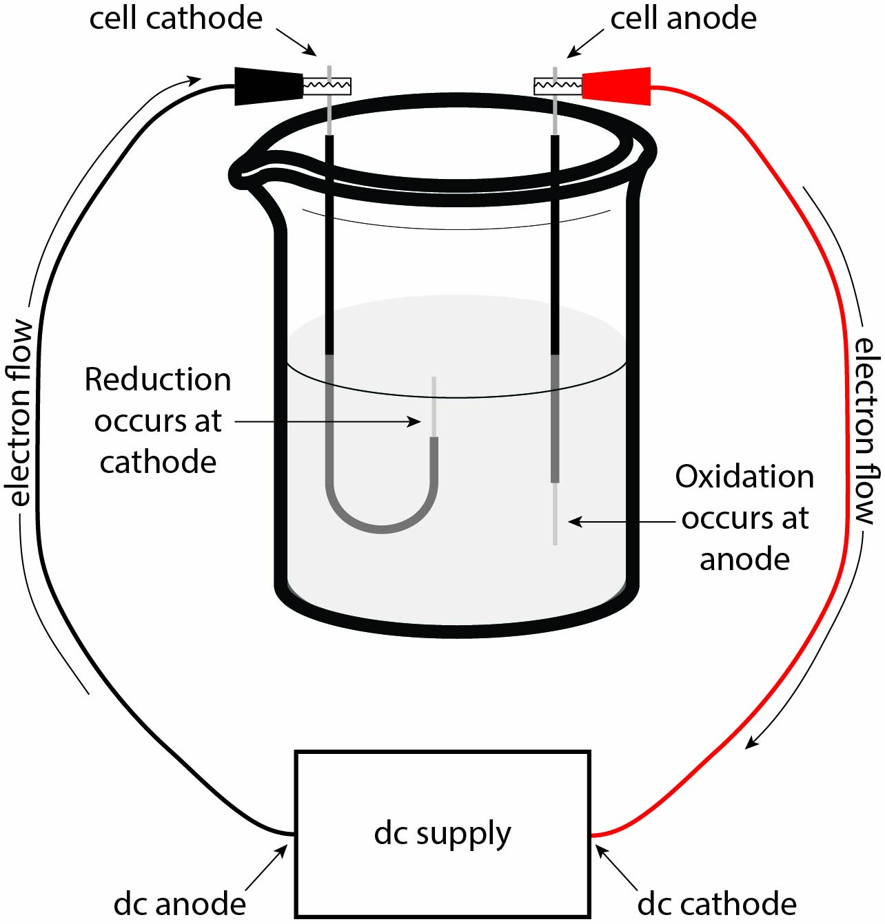
The completed circuit results in potential energy being generated between the anode and cathode in the cell, and this electrical potential can be leveraged in chemical reactions. As negative charge builds up in the cell’s cathode, the positive ions in the solution are attracted to the negatively–charged cathode, while the negative ions in the solution are repelled away and subsequently attracted to the positively–charged anode. The increased electrical potential at the cathode allows for non-spontaneous reduction to occur, such as that outlined in equation 1. On the other hand, this same electrical potential at the cell’s anode allows for non-spontaneous oxidation to occur.
Tips and Tricks: This may seem like a lot of large words that you are unfamiliar with, and that’s completely okay! Take a few seconds to look over and understand the electrolytic cell in Figure 1. Try to familiarize yourself with where electrons are flowing and what effect the electron build-up (or absence) will have on the ions in the solution. The video linked here has a good description of the setup of an electrolytic cell and allows you to actually see the chemistry occurring at each electrode.
Redox Stoichiometry, Faraday’s Constant, and Avogadro’s Number
An important cornerstone of redox reactions is that the number of electrons lost by the oxidized species must equal the number of electrons gained by the reduced species. This means that electrons can be treated stoichiometrically just like any other reactant or product. Additionally, the number of moles of product formed is related to the number of moles of electrons that pass through the cell during electrolysis. These relationships allow us to experimentally determine both Faraday’s constant and Avogadro’s number.
Before exploring Faraday’s constant, let’s take a moment to talk about common units in electrochemistry and what they mean. To start, we can consider the ampere, or amp. An amp (written as A) is a measure of electrical current, or simply how fast the electrons are flowing through the conducting material and has a standard value of 6.28•1018 electrons per second. A coulomb (written as C) is a measure of how much electric charge passes through an electrical conductor when 1 amp of electricity flows for one second. A faraday (or Faraday’s constant, written as F) is a measure of the charge on a single mole of electrons and has a value of 9.650•104 C/mol.
In this lab, we will be using an ammeter (a device used to measure current in an electrical system) to determine the current flowing through our system, which will then allow us to determine the total charge (in coulombs) that passed through the system over a given period of time. By relating the total charge and the number of moles of electrons transferred, we can then determine the value of Faraday’s constant.
Finally, remember that electrons can be treated stoichiometrically like other chemical species. This means that after determining the number of electrons transferred from the amount of H2 gas generated, we can determine the value of Avogadro’s number. As a reminder, Avogadro’s number is specifically the number of electrons in a mole of electrons (though it is often applied as the number of anything in a mole of that thing). So, knowing that one electron has a charge of 1.6022•10-19 coulombs, we can confirm that value of Avogadro’s number.
Experiment Overview
During this experiment, we will be studying the reaction that occurs when a steady electrical current is passed through a solution of potassium iodide. Much like in the voltaic cell experiment, we can break this down into two half–reactions that are occurring simultaneously — one half–reaction occurs at the anode, the other occurring at the cathode.
| Anode (oxidation half–reaction): 2I−(aq) → I2(aq) + 2e− | (2) |
| Cathode (reduction half–reaction): 2H2O(l) + 2e− → H2(g) + 2OH−(aq) | (3) |
| Overall Reaction: 2I−(aq) + 2H2O(l) → I2(aq) + H2(g) + 2OH−(aq) | (4) |
There are a few indicators that we can keep an eye out for that show the reaction is proceeding as we expect. First, the reaction results in the formation of hydrogen gas. As you would expect, the gas will readily leave the solution in the form of small bubbles. Second, the molecular iodine that’s formed will react with acetone that is also added to the solution (omitted up until this point to avoid confusion). The iodine reacts with acetone through what’s called the “iodoform reaction” to form (you guessed it) iodoform, which is CH3I. Iodoform dissolves in water to form a yellow solution, so as the reaction progresses, the solution will become darker yellow as the amount of H2 gas increases as well.
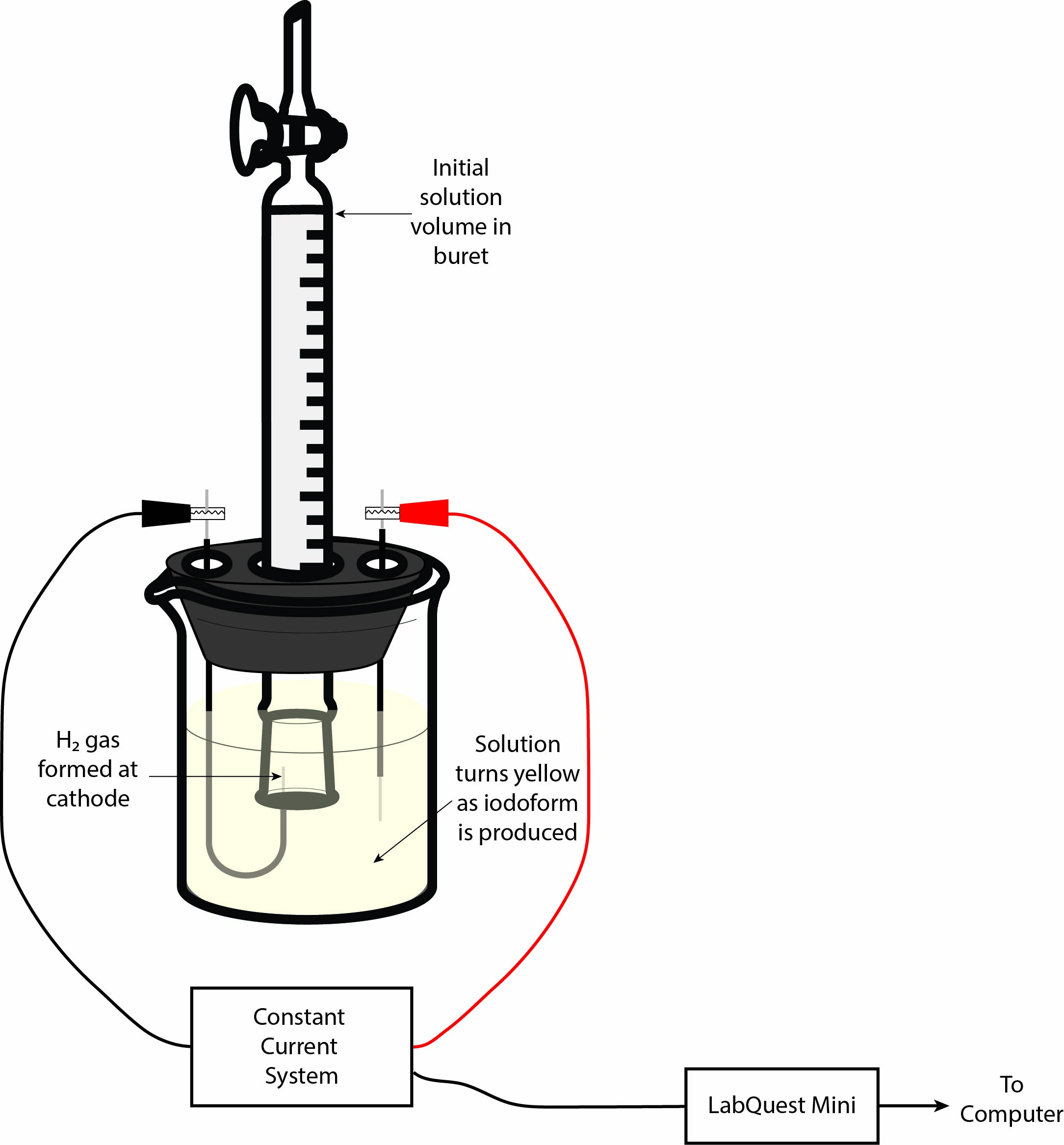
In order to gain meaningful insight into how the electrolysis is progressing, we need to be able to quantify how much hydrogen gas has been formed. To do this, we will draw some of the solution up into an inverted 10 mL buret and place the mouth of the buret over the cathode wire. This will trap all of the H2 gas in the buret by displacing the solution. So, we can directly measure the volume of hydrogen gas formed by finding the difference between the starting and final volume of liquid in the buret. From there, we can use the volume of H2 gas produced to determine the number of electrons transferred, thereby allowing for the determination of the constants mentioned above. Figure 2 shows a sketch of the experimental setup to help you understand how your setup should look before you begin. As always, you can (and should!) ask your TA to confirm that your setup is correct before continuing.
Tips and Tricks: When you arrive in the lab, you’ll notice that the cells should be set up for you. The two electrodes will already be inserted into the stopper — one J-shaped cathode and one straight anode. We recommend that you check the electrodes first! Both electrodes should have a thin piece of metal wire sticking out of both ends of the electrodes. If you see that either electrode is missing one of these metal wires, let your TA know so it can be replaced quickly.
Experimental Procedure
Before beginning, make sure to record the pressure and temperature in the lab — you will need these values during your data workup! The electrolytic cell should already be set up for you at your workstation. The cell consists of a stoppered 50 mL beaker, with a J-shaped glass cathode, a straight glass anode, and an inverted 10 mL buret in the middle. Remove the stopper from the 50 mL beaker and measure about 1.67 g of KI into the beaker using an analytical balance. Next, add about 30–40 mL of DI water to the beaker and swirl it around until all of the KI is dissolved. Once all of the KI is dissolved, add around 0.5 mL of acetone to the KI solution and gently swirl it by hand to mix it together. Finally, drop in a small stirbar and place the beaker onto your stirplate.
Reassemble your electrolytic cell by putting the stopper in the beaker such that the electrodes are completely submerged in the KI solution and then lower the buret over the J-shaped cathode. The buret should completely cover the small metal wire coming out of the glass end of the cathode, but should not be touching the glass of the cathode. Having this space will allow solution to flow out of the buret as hydrogen gas is produced. Turn the stirplate on to a low setting and make sure that the stir bar is not aggressively hitting either of the glass electrodes.
Now we need to fill the inverted buret with some of the solution from the beaker. To do this, grab a pipette bulb from the general supplies bench and open the stopcock on the buret (the stopcock should be parallel to the glass of the buret). Squeeze the pipette bulb and gently place it onto the tip of the buret, being careful to not jam the bulb on it too hard. As you allow the pipette bulb to reinflate, you should notice that solution rises from the beaker into the buret. Fill the buret until the liquid level is around the 10 mL mark (this should be the top-most mark when the buret is inverted). Be sure to close the stopcock before removing the pipette bulb!
Tips and Tricks: While you’re filling the buret, you might realize that the solution won’t be able to reach the 10 mL mark before the pipette bulb is completely reinflated. In that case, you should close the stopcock and then carefully remove the pipette bulb. With the stopcock closed, there is no way for air to fill the headspace above the liquid level. This means that the liquid in the buret will not drain, despite removing the pipette bulb. Now you can squeeze the bulb again, place it on the tip of the buret, open the stopcock, and finish filling the buret.
To finish the setup of the electrolytic cell, connect the black lead from the dc supply to the J-shaped cathode and the red lead to the straight anode. Do not plug the dc supply into the power source yet! Now that the cell is set up, let’s get the Vernier Constant Current System set up.
Connect the LabQuest Mini to the computer using the USB cable, and connect the Constant Current System to the LabQuest Mini in Channel 1. With these set up, you can open the Logger Pro software on the computer. At the main window, click on the “Experiment” tab, then click on “Data Collection”. Change the Sampling rate to 1 sample/second, and click the “Save” button. Make sure that the voltage knob on the Constant Current System is turned all the way up.
At this point, everything should be completely set up, but the Constant Current System should still be unplugged from the wall. When you are ready to begin, plug the Constant Current System into the wall to begin the electrolysis and immediately click the “Collect” button. You’ll be able to tell that the reaction has started by the presence of bubbles rising up into the buret and the KI solution should start to slowly turn yellow as iodoform is formed. All the reaction to progress until about 8–9 mL of H2 gas have been collected.
Once you’ve collected ~9 mL of hydrogen gas, click the “Stop” button and immediately unplug the Constant Current System from the wall. Once all of the bubbles have rising to the top of the buret (you may need to wait a couple of minutes), take a final volume reading based on the level of the liquid remaining in the buret. Be sure to record the total experiment time that appears in the LoggerPro data! Use a ruler to measure the distance (in mm) from the level of the solution remaining in the buret to the top of the solution inside the beaker. This will represent the Pwatercolumn value that you will need later in the data workup section.
On the Logger Pro software, click on the “Integrate” button. This will take the area under the Current (in amperes) vs. Time (in seconds) curve, which is equal to the total charge (in coulombs) that was transferred during the experiment. Finally, press the “Statistics” button in Logger Pro. This will give you the average current that passed through the cell during the experiment. Multiply this average by the duration of current flow in the experiment. How does this value compare to the value you obtained from the integration function?
You may clean up by discarding the KI solution in the proper Inorganic waste jug. The inside of the buret and beaker should be rinsed with acetone and again disposed of in the inorganic waste jug. Place the cleaned buret upside-down on the ring stand with the stopcock open, and leave the electrolytic cell setup at your station.